Connect the Circuit
In the very first of this experiment, we have to connect the circuit. There is three parts waited to be connect. First, connect the ST-LINK. Second, conect the CP2012. And finally, connect the button to pins on STM32.
Connect ST-LINK
In order to get through the ST-LINK, two steps must be done. The very first step is connect the pins with Dupont Lines. Here is the corresponding pins.
| ST-LINK | STM32 |
|---|---|
| SWCLK | DCLK |
| SWDIO | DIO |
| GND | GND |
| 3.3V | 3.3V |
Next, the driver must be installed.
Connect CP2012
Similarly, I will give the corresponding pins talbe.
| CP2012 | STM32 |
|---|---|
| 3.3v | 3.3v |
| GND | GND |
| TXD | A10 |
| RXD | A9 |
And, of course, make sure driver running correctly.
Connect Button
There are two four ports in one button. In order to input separtely, only two ports could be used. One is connected to ‘GND’ and one is connected to ‘PA11’ or ‘PA12’.
Here is the circut diagram.
Configuration
In my opinion, there is some configuration need to be mentioned.
Comment Removal
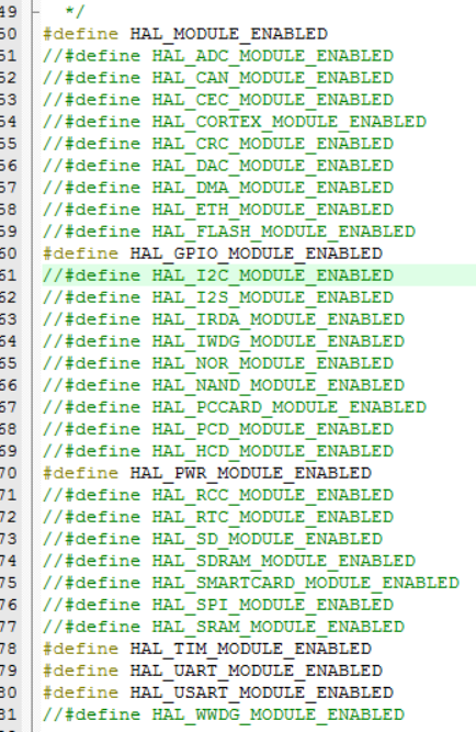
The some comment mark in stm32f1xx_hal_conf.h must be remove, so that the compiler would link them into executable.
Especially, following two #define must be released. Because we must use UART, TIM and GPIO.1
2
3
Programming Algorithm
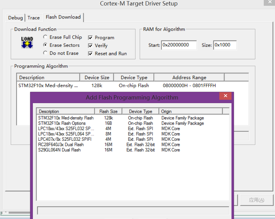
The Programming Algorithm must be added, otherwise, we couldn’t program. You could find this dialog in given documentation.
Initialize UART
One handler must be defined, so that we could initialize with it.1
UART_HandleTypeDef UartHandler;
This variable could be global or local. Next, set parameters and initialize.1
2
3
4
5
6
7
8UartHandler.Instance = USART1;
UartHandler.Init.BaudRate = 9600;
UartHandler.Init.WordLength = UART_WORDLENGTH_8B;
UartHandler.Init.StopBits = UART_STOPBITS_1;
UartHandler.Init.Parity = UART_PARITY_NONE;
UartHandler.Init.HwFlowCtl = UART_HWCONTROL_NONE;
UartHandler.Init.Mode = UART_MODE_TX_RX;
HAL_UART_Init(&UartHandler);
Rewrite Output
Our intent is use printf function write the data to the serial port. So, two function need to be rewritten, which are int __io_putchar(uint8_t ch) and int fputc(int ch, FILE *f) respectively.1
2
3
4
5
6
7
8
9
10int __io_putchar(uint8_t ch){
HAL_UART_Transmit(&UartHandler, &ch, 1, 100);
return 1;
}
int fputc(int ch, FILE *f){
uint8_t chr =ch;
HAL_UART_Transmit(&UartHandler, &chr, 1, 100);
return 1;
}
Now the output would be directed to the serial port.
GPIO Initilization
Two pins must be initilized, PA11 and PA12.1
2
3
4
5
6
7
8
9
10
11
12
13
14
15
16
17
18GPIO_InitTypeDef GPIO_InitStruct;
__GPIOA_CLK_ENABLE();
GPIO_InitStruct.Pin = GPIO_PIN_11;
GPIO_InitStruct.Mode = GPIO_MODE_INPUT;
GPIO_InitStruct.Pull = GPIO_PULLUP;
GPIO_InitStruct.Speed = GPIO_SPEED_LOW;
HAL_GPIO_Init(GPIOA, &GPIO_InitStruct);
GPIO_InitStruct.Pin = GPIO_PIN_12;
GPIO_InitStruct.Mode = GPIO_MODE_IT_FALLING;
GPIO_InitStruct.Pull = GPIO_PULLUP;
GPIO_InitStruct.Speed = GPIO_SPEED_LOW;
HAL_GPIO_Init(GPIOA, &GPIO_InitStruct);
HAL_NVIC_SetPriority(EXTI15_10_IRQn,0,0);
HAL_NVIC_EnableIRQ(EXTI15_10_IRQn);
The function HAL_GPIO_Init(GPIOA, &GPIO_InitStruct) would call void HAL_UART_MspInit(UART_HandleTypeDef *huart) in stm32f1xx_hal_msp.c. Thus we must fill the code.1
2
3
4
5
6
7
8
9
10
11
12
13
14
15
16
17
18
19
20
21void HAL_UART_MspInit(UART_HandleTypeDef *huart)
{
__HAL_RCC_GPIOA_CLK_ENABLE();
__HAL_RCC_USART1_CLK_ENABLE();
GPIO_InitTypeDef GPIO_InitStruct;
GPIO_InitStruct.Pin = GPIO_PIN_9;
GPIO_InitStruct.Mode = GPIO_MODE_AF_PP;
GPIO_InitStruct.Speed = GPIO_SPEED_HIGH;
HAL_GPIO_Init(GPIOA, &GPIO_InitStruct);
GPIO_InitStruct.Pin = GPIO_PIN_10;
HAL_GPIO_Init(GPIOA, &GPIO_InitStruct);
}
void HAL_UART_MspDeInit(UART_HandleTypeDef *huart)
{
__HAL_RCC_USART1_FORCE_RESET();
__HAL_RCC_USART1_RELEASE_RESET();
HAL_GPIO_DeInit(GPIOA, GPIO_PIN_9);
HAL_GPIO_DeInit(GPIOA, GPIO_PIN_10);
}
If __GPIOA_CLK_ENABLE() is not called, the input of PA11 would be strange, like a clock. Thus you shouldn’t forget it. And HAL_NVIC_SetPriority(EXTI15_10_IRQn,0,0) and HAL_NVIC_EnableIRQ(EXTI15_10_IRQn) would set the interrupt for PA12. Now, we need a callback function to handle the push.
Add a function in stm32f1xx_it.c to handle the interrupt.1
2
3void EXTI15_10_IRQHandler(void){
HAL_GPIO_EXTI_IRQHandler(GPIO_PIN_12);
}
This function would call void HAL_GPIO_EXTI_Callback(uint16_t GPIO_Pin), so it’s necessary to implement it in main.c.1
2
3void HAL_GPIO_EXTI_Callback(uint16_t GPIO_Pin){
counter++;
}
According to the requirement, we need to increase counter. So far, we’ve handle the input of PA12. Next, we would handle the PA11 in main loop. Add following code snipet in int main(void)1
2
3
4if ((HAL_GPIO_ReadPin(GPIOA, GPIO_PIN_11))==0) {
printf("Pressed\r\n");
mode=!mode;
}
Change the mode, of course, and remember that, this condition statement must be enclosed by a loop.
Timer Initialization
Follwing code snippet is to set the serial port parameters. However, I don’t the specific meaning of this statements.1
2
3
4
5
6
7
8
9
10
11
12
13
14
15
16TIM_ClockConfigTypeDef sClockSourceConfig;
TIM_MasterConfigTypeDef sMasterConfig;
TIM_Handler.Instance = TIM3;
TIM_Handler.Init.Prescaler = 48000;
TIM_Handler.Init.CounterMode = TIM_COUNTERMODE_UP;
TIM_Handler.Init.Period = 199;
TIM_Handler.Init.ClockDivision = TIM_CLOCKDIVISION_DIV1;
HAL_TIM_Base_Init(&TIM_Handler);
sClockSourceConfig.ClockSource = TIM_CLOCKSOURCE_INTERNAL;
HAL_TIM_ConfigClockSource(&TIM_Handler, &sClockSourceConfig);
sMasterConfig.MasterOutputTrigger = TIM_TRGO_RESET;
sMasterConfig.MasterSlaveMode = TIM_MASTERSLAVEMODE_DISABLE;
HAL_TIMEx_MasterConfigSynchronization(&TIM_Handler, &sMasterConfig);
Then call this function1
HAL_TIM_Base_Start_IT(&TIM_Handler);
And this function cooperate with other two function that we must implement in stm32f1xx_hal_msp.c.1
2
3
4
5
6
7
8
9
10
11
12
13
14
15
16
17
18
19void HAL_TIM_Base_MspInit(TIM_HandleTypeDef* htim_base)
{
if(htim_base->Instance==TIM3)
{
__TIM3_CLK_ENABLE();
HAL_NVIC_SetPriority(TIM3_IRQn, 0, 0);
HAL_NVIC_EnableIRQ(TIM3_IRQn);
}
}
void HAL_TIM_Base_MspDeInit(TIM_HandleTypeDef* htim_base)
{
if(htim_base->Instance==TIM3)
{
__TIM3_CLK_DISABLE();
HAL_NVIC_DisableIRQ(TIM3_IRQn);
}
}
Similarly, we need to append a handler in stm32f1xx_it.c.1
2
3
4void TIM3_IRQHandler(void)
{
HAL_TIM_IRQHandler(&TIM_Handler);
}
And the function HAL_TIM_IRQHandler(&TIM_Handler) would call a callback function whose name is void HAL_TIM_PeriodElapsedCallback(TIM_HandleTypeDef *htim). Just like the condition above, the implementation is necessary.
void HAL_TIM_PeriodElapsedCallback(TIM_HandleTypeDef *htim){
    if(htim->Instance == TIM3){
        timer_flag = 1;
        timer_counter++;
    }
}
Result
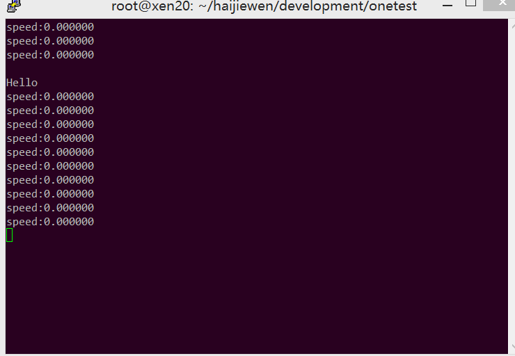
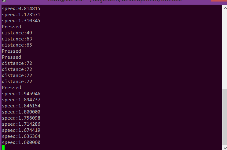
Finally, we could check the results.
Print Hello as request.
Press PA11 to change the mode and press PA12 to increment distance. The timer counter is always accumalted. For now, I’ve finished the required part.